Planned research · not yet implemented
FUTURE PROJECT A · INTELLIGENT TRANSPORTATIONGround Traffic Control System (GTCS)
An ATC-inspired traffic surveillance, tracking and decision-support platform for civilian road networks.
GTCS is a planned project that would treat road traffic the way an air-traffic control system treats airspace: not just detecting vehicles in camera images, but building a continuous traffic picture, tracking moving road users, estimating how traffic is evolving, and supporting an operator's decisions.
It applies the engineering pattern I have worked with in C4I/C2 systems, radar multi-target tracking and multi-sensor fusion to a civilian domain. The plan starts with one camera at one intersection and grows only as each stage is measured and validated.
- Status
- Planned research & development; no component has been built yet
- Builds on
- Radar MTT, multi-sensor fusion, C2 data exchange, GPS tracking
- First milestone
- One fixed camera, recorded video, one complete tracking pipeline
- Target domain
- Civilian intelligent transportation and smart-city traffic centres
Problem & motivation
From Camera Feeds to a Traffic Picture
Many traffic centres already have cameras. What is often missing is a coherent operational picture: an operator watches a wall of video feeds and has to judge, by eye, where queues are growing, which road is blocked, and whether an alternative route would actually be faster.
Air-traffic control solved a similar problem decades ago. Surveillance sensors produce plots, a tracker turns plots into continuous tracks, fusion combines sensors into one air picture, and decision-support tools help a controller act. GTCS proposes to bring that same chain to road traffic: detect → track → estimate → fuse → detect events → recommend → authorise → evaluate.
Roads are not airspace, though. A road system has signals, intersections, pedestrians, lane capacity, queues and very different user behaviour. GTCS can reuse the underlying engineering concepts, but its traffic models, alert logic and safety procedures must be designed specifically for roads.
Five planned capabilities
Traffic surveillance
Detect vehicles, buses, trucks, motorcycles, bicycles and, where appropriate, pedestrians in road-camera video.
ATC analogue: surveillance sensor inputVehicle tracking & data fusion
Maintain tracks over time, estimate position, velocity and direction, and associate observations across cameras where feasible.
ATC analogue: track initiation, tracking, correlationCommon traffic picture
Combine tracks, road geometry, signal states, queues and traffic measurements into one map-based picture.
ATC analogue: Common Operational PictureDecision support
Detect congestion and incidents, rank alerts by severity and recommend interventions or alternative routes.
ATC analogue: controller decision supportIntervention & evaluation
Present recommendations to an authorised operator and measure their effect; integrate signal controllers only later, through approved interfaces.
ATC analogue: instruction and feedback, adapted for roads
Proposed architecture
A Distributed Surveillance-to-Decision Architecture
Cameras and edge computers would collect and pre-process data, a central server would build the traffic picture, and operator workstations would provide supervision and decision support. Separating perception, tracking, traffic analysis and decision-making keeps each layer testable on its own.
GTCS layered architecture
Proposed design-
Surveillance layer
- IP road cameras
- Recorded video
- Optional radar / loop detectors
-
Edge processing
Object detection
Boxes, class, confidence, timestamp, camera ID per frame.
Single-camera tracking
Kalman-based tracks with temporary IDs.
-
Central GTCS processing server
Track management & fusion
Association, motion estimation, duplicate-track handling.
Road network & map matching
Tracks placed on lanes and road segments.
Traffic-state estimation
Flow, speed, occupancy, queues, travel time.
Incident detection & decision support
Congestion, queue growth, abnormal stops, routes.
-
Ground Traffic Control Centre
- Digital traffic map
- Camera wall
- Alerts
- Operator decisions
- Performance reports
Messages between layers carry timestamps and source IDs so that every traffic measurement can be traced back to the observations that produced it.
Why this split
- Edge detection and tracking keep raw video near the camera and send compact observations upstream, which limits network load.
- Central fusion sees all cameras, so it is the right place to resolve duplicate tracks and associate vehicles between overlapping or adjacent views.
- Traffic-state estimation works on road segments rather than pixels, so map-matched results can be compared with field counts and other sensors.
- Operator-centred output keeps a human in the loop: GTCS recommends, the authorised operator decides.
Processing pipeline
How Detection, Tracking, Estimation and Fusion Work Together
Each stage answers a different question. The detector says what is in this frame; the tracker says which detections are the same vehicle over time; estimation says where it is on the road and how fast it moves; fusion says what the road network is doing.
Frame acquisition
Read video with accurate timestamps and camera IDs; flag dropped or late frames.
out: frame, t, camera_idVehicle detection
A YOLO-family detector (or equivalent) produces boxes, class and confidence. On its own it has no notion of identity across frames.
out: box, class, scoreSingle-camera tracking
Associate detections with predicted tracks, update with a Kalman filter, and manage initiation, missed detections and termination.
out: track_id, state, covarianceRoad-plane calibration
Map the bottom-centre of each box through a calibrated homography so that motion is measured in metres, not pixels.
out: X, Y on road planeTraffic measurements
Per vehicle: lane or segment, direction, speed (where calibration supports it), stop duration, entry/exit times and turning movement.
out: per-vehicle measurementsMulti-camera fusion
Combine measurements from several cameras; associate tracks across views using geometry, timing and road topology before appearance.
out: fused tracks / segment statesTraffic-state estimation
Aggregate into flow, average speed, occupancy, queue length and travel time per road segment and time window.
out: segment state, t-windowEvents & decision support
Detect congestion and candidate incidents with persistence checks; compute alternative routes; present ranked recommendations.
out: alerts, recommendations
Two separate fusion problems
- Sensor fusion — combining measurements from different sources to estimate the traffic state of a road segment.
- Cross-camera track association — deciding whether a vehicle leaving one camera's view is the same vehicle entering another's.
The plan starts with known camera positions, calibrated fields of view, road topology, synchronised timestamps and feasible travel-time windows. Appearance features add evidence only where permitted. Colour or proximity alone does not establish identity: occlusions, similar vehicles and clock offsets all cause false associations. For the first version it is entirely reasonable to fuse aggregated traffic measurements rather than maintain one vehicle identity across a city.
A track ID is not an identity. GTCS would track road users for traffic analysis without assuming it knows who they are. No licence-plate recognition or personal identification is part of this plan.
Mathematical foundations
Tracking, Calibration and Traffic-State Models
The starting models are deliberately simple and well understood, so that every later improvement can be measured against a clear baseline. The worked numbers below are arithmetic examples, not measurements.
Constant-velocity state on the road plane
- Vehicle reference point on the calibrated road plane (metres).
- Velocity components (m/s).
- Time between processed frames, taken from timestamps — not assumed constant.
- Measurement matrix selecting position: the detector measures where a vehicle is, not its velocity.
- Process noise (unmodelled acceleration, covariance ) and measurement noise (detection jitter, covariance ).
Validation gate on the innovation
A detection is a candidate for a track only if its normalised distance from the prediction is inside the gate. This is the same plot-to-track gating idea used in radar tracking; in video, an IoU-based cost is a common complementary test while tracking in image space.
- Innovation: difference between the detection and the predicted position.
- Innovation covariance — how uncertain the prediction and detection are together.
- Gate threshold, e.g. a chi-square quantile for 2 degrees of freedom (≈ 9.21 for 99 %).
Image-to-road homography
is estimated from at least four surveyed image-to-ground point correspondences (more in practice, with a least-squares fit). It is only valid for points on the road surface, which is why the bottom-centre of a bounding box is used rather than its centre. Road crowning, slopes and lens distortion limit accuracy and are part of the validation plan.
- Pixel coordinates in the (undistorted) image.
- Arbitrary scale factor of homogeneous coordinates.
Flow, density and speed
- Vehicles crossing a reference line during the interval .
- Flow, e.g. vehicles per minute or per hour (units always stated).
- Density: vehicles per kilometre of lane.
- Space-mean speed. The relation holds for averages under roughly stationary traffic, not for individual vehicles.
Arithmetic example: 36 vehicles crossing the line in 2 minutes gives veh/min, i.e. 1,080 veh/h.
The city as a directed graph
- Intersections and other network nodes.
- Directed road segments, each with length, legal direction, capacity, restrictions and an estimated travel time.
The traffic-state estimator updates each edge's condition, so the graph always reflects the latest measured traffic rather than static map distances.
Time-dependent travel-time cost
- Segment length.
- Estimated speed on the segment at time .
- Floor that prevents division by zero when traffic stops.
- Time the vehicle is expected to reach segment .
Arithmetic example: a 600 m segment at 5 m/s costs 120 s; a 900 m alternative at 12 m/s costs 75 s — the longer route is faster. Queues, closures, turning delays and signal phases must later be added to this simplified model.
Traffic command & control
Decision Support with an Operator in the Loop
This is what would distinguish GTCS from a conventional monitoring application: an explicit operational loop and an alert lifecycle, modelled on the status management I have implemented in command-and-control software.
- ObserveVideo, sensor measurements and signal-state information.
- EstimateTracks, flow, queues and segment conditions.
- DetectCongestion, incidents, abnormal stops, deterioration.
- RecommendGenerate and rank traffic-management actions.
- AuthoriseAn authorised operator reviews and decides.
- EvaluateMeasure the outcome and update the estimate.
The loop repeats continuously; evaluation feeds the next observation cycle.
Example scenario (planned behaviour)
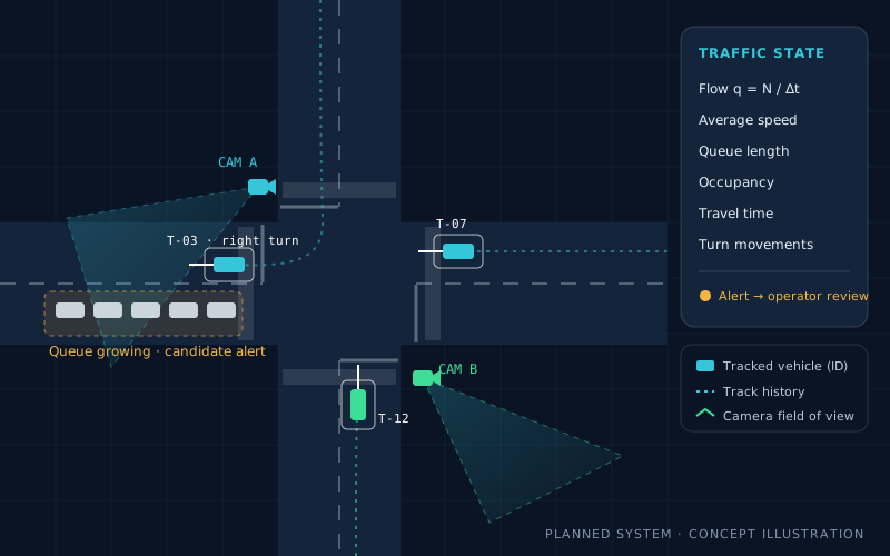
Camera A watches the approach to an intersection; Camera B watches the downstream road. GTCS would notice that:
- the queue on the approach is growing,
- the average speed is falling,
- downstream traffic is also slow, and
- an alternative route has a lower estimated travel time.
The operator would receive one alert containing the affected road, the measured conditions, a confidence level and suggested actions: publish an alternative route to authorised information systems, request a signal-timing review, investigate a possible obstruction, or coordinate with another team.
No automatic signal control. Early phases would only recommend and simulate. Real controllers would be connected only through approved interfaces, with safety checks, authorisation and fallback procedures, and only after validation.
Alert lifecycle
- Detected
- Verified
- Acknowledged
- Action proposed
- Authorised
- Monitoring
- Resolved
| State | Meaning |
|---|---|
| Detected | An algorithm has identified a potential event. |
| Verified | Reviewed or corroborated by another source. |
| Acknowledged | An operator has confirmed awareness. |
| Action proposed | The system has generated a recommendation. |
| Authorised | The responsible operator approved the action. |
| Monitoring | The system is measuring the outcome. |
| Resolved | The condition has cleared or the event is closed. |
Traffic-management algorithms, built progressively
- A
Traffic-flow estimation
Counts, flow, average speed and occupancy over defined time windows.
- B
Queue & congestion detection
Combine falling speed, queue growth, occupancy and travel-time change; set thresholds from recorded data and validate against manual observation.
- C
Incident detection
Stationary vehicles in a live lane, sudden queues, unexpected flow interruption — with temporal persistence and corroboration to limit false alarms.
- D
Alternative routes
Shortest-time paths on the road graph with time-dependent edge costs and road restrictions.
- E
Signal-timing studies
In simulation only: fixed-time versus traffic-responsive plans, compared on queue, delay, throughput and pedestrian requirements.
- F
System health
Camera availability, stale or missing data and processing latency, surfaced as alerts in their own right.
Proposed hardware & software
Implementation Technologies
Proposed choices, not technologies already integrated into GTCS. A normal development computer is enough for the first prototype; a GPU or edge accelerator would be added when the detector and real-time throughput requirements justify it.
| Component | Proposed technology | Purpose |
|---|---|---|
| Operating system | Ubuntu Linux LTS | Edge computers and central server |
| Video processing | Python, OpenCV | Streams, frame handling, calibration |
| Vehicle detection | YOLO-family detector or equivalent | Detect road users |
| Object tracking | ByteTrack or similar, with Kalman filtering | Maintain temporal tracks |
| Cross-camera matching | Geometric constraints + appearance association | Link observations across cameras |
| Map & spatial data | PostgreSQL / PostGIS | Road geometry, intersections, geospatial records |
| Event messaging | MQTT or another message broker | Distribute observations and events |
| Backend API | FastAPI | Expose traffic data and services |
| Operator interface | PyQt5 first, or a browser front end | Traffic control workstation |
| Visualisation | OpenStreetMap-compatible or approved local maps | Roads, tracks, queues, alerts |
| Simulation | SUMO | Test strategies before any real infrastructure |
| Reporting | Python analytics, PDF generation | Statistics and incident reports |
Data sources for development
Development would begin without installing cameras around a city, using public or permitted recorded footage:
- UA-DETRAC — traffic surveillance video with vehicle annotations.
- AI City Challenge resources — traffic analytics and multi-camera tracking research.
- Ultralytics YOLO and OpenCV documentation — detection, tracking and calibration tooling.
- SUMO — traffic-control experiments in simulation.
Each dataset's licence and usage conditions would be checked before any commercial demonstration.
Software traceability rule
Every detection has a timestamp, every track has a defined lifecycle, and every traffic measurement can be traced back to its source observations.
Engineering challenges & limitations
What Makes This Hard
- Perception
Occlusion & dense traffic
Vehicles hide each other in queues and at intersections, causing missed detections and identity switches.
Approach: track coasting with growing uncertainty, careful gating and metrics that count ID switches explicitly.
- Conditions
Night, rain, glare
Detector performance varies with lighting, weather and camera quality.
Approach: evaluate separately per condition and report where performance drops rather than one average.
- Geometry
Calibration accuracy
Homography assumes a flat road; slopes, crowning and lens distortion add error to positions and speeds.
Approach: surveyed reference points and speed checks against an independent reference before any speed is reported.
- Timing
Clock synchronisation
Unsynchronised cameras break cross-camera association and travel-time estimates.
Approach: NTP/PTP-synchronised sources and explicit timestamp-offset measurement.
- Alerts
False alarms
An alert system that cries wolf will be ignored by operators.
Approach: persistence checks, corroboration across measurements, and false alerts per hour as a primary metric.
- Governance
Privacy & authority
Video of public roads is sensitive, and traffic infrastructure belongs to authorities.
Approach: no identification of individuals, aggregated outputs, and integration only with authorised systems.
Testing & performance metrics
How GTCS Would Be Measured
A credible demonstration needs measured results, not just an impressive interface. Target values will be set only after a baseline exists for the actual camera conditions; no real-time or accuracy figure is claimed before it has been measured under representative conditions.
| Subsystem | Metrics | Reference |
|---|---|---|
| Vehicle detection | Precision, recall, false detections | Annotated frames |
| Vehicle tracking | ID switches, track continuity, IDF1 or HOTA | Annotated trajectories |
| Speed estimation | Mean absolute error | Independent speed reference |
| Vehicle counting | Absolute and percentage counting error | Manual counts |
| Queue estimation | Difference from manually measured queue length | Manual review |
| Congestion detection | Precision, recall, false alerts per hour | Labelled congestion periods |
| Incident detection | Detection delay, false-alarm rate | Labelled events |
| Route recommendation | Predicted versus observed travel time | Observed trips |
| Processing system | End-to-end latency, throughput, dropped frames | Instrumented pipeline |
| Operational reliability | Camera availability, stale-data alerts, recovery time | System logs |
Phased implementation roadmap
Seven Phases, Each Testable on Its Own
Every phase ends with a working, demonstrable result. Full-city coverage, automated signal control and citywide vehicle identity are explicitly not where the project starts.
- P1First milestone
Single-camera prototype
- Process recorded traffic video
- Detect vehicles, assign track IDs
- Draw boxes and trajectories
- Show timestamps and processing performance
Deliverable: a working video-tracking demonstration.
- P2
Tracking & traffic measurements
- Calibrate the camera
- Road-plane positions and speeds
- Count vehicles and turning movements
- Queue lengths and travel times
Deliverable: analytics validated against manually reviewed video.
- P3
Digital traffic situation display
- Interactive road map
- Camera locations, conditions, statistics
- Trajectories where appropriate
- Alerts and historical playback
Deliverable: a first GTCS operator interface.
- P4
Multi-camera integration
- At least two camera streams
- Synchronised timestamps
- Combined traffic measurements
- Cross-camera association experiments
Deliverable: a coordinated picture of two connected road sections.
- P5
Traffic C2 & decision support
- Congestion and candidate incidents
- Alert acknowledgment and resolution
- Alternative routes
- Recommendations with evidence
Deliverable: a decision-support workflow with operator authorisation.
- P6
Simulation & optimisation
- Model a small intersection or corridor
- Feed measurements into a simulator
- Test signal-timing strategies
- Compare delay and queues before/after
Deliverable: a repeatable, measurable traffic-management experiment.
- P7
Field pilot
- Approved cameras at a real site
- Calibrated road geometry
- Automated vs. field observations
- Day, night, weather and occlusion tests
Deliverable: a documented pilot with measured performance and known limitations.
Prototype V1 scope: one fixed camera with recorded video, detection and single-camera tracking, Kalman-based motion estimation, road-plane calibration, counting/flow/queue estimation, an intersection layout, a PyQt5 operator interface, alerts with an event log, a simulated route-recommendation workflow and a recorded end-to-end demonstration.
Expected contribution
Expected Contribution & Research Direction
GTCS would extend my experience in C4I/C2 systems, radar tracking, multi-sensor data fusion, GPS navigation and real-time software into civilian intelligent transportation. The distinctive contribution is not any single algorithm, but an end-to-end engineering chain — surveillance, tracking, fusion, traffic-state estimation and operator decision support — in which every output is traceable and measured.
Potential applications
- Urban traffic management and smart-city operations centres
- Corridor and intersection performance studies
- Incident awareness for road operators
- Evidence-based signal-timing and route-guidance studies

Mohammed Ismail Ali Attala
Senior Systems Engineer · C4I/C2 Integration · Tracking & Navigation
Open to discussing GTCS with traffic authorities, ITS integrators and research partners.
Contact & Collaboration
Working on Intelligent Transportation?
I welcome discussions about traffic surveillance, vehicle tracking, traffic-state estimation and decision-support systems with transport authorities, integrators and research teams.